In this post I want to
describe the simplest program, which transferring bytes from our
board using UART and SPI interfaces.
First of all, we should
setup our pins. I will do it in CubeMX, though if you want to deeper
understand these interfaces, you can read through datasheets and set
up them manually.
UART
UART is for Universal
Asynchronous Receiver-Transmitter. There are several pins in UART, in most common configuration:
1. RX – this is an input
pin.
2. TX – this is an output
pin.
3. RTS – this is a control
line signal (optional).
4. CTS – this is a control
line signal (optional).
In this introductщкн material we are going to use only TX pin, because we want only to
transmit bytes.
Let's use a board configuration
from the last post:
To see what settings have been applied, go to the
usart.c file.
void MX_USART2_UART_Init(void)
{
  huart2.Instance = USART2;
  huart2.Init.BaudRate = 115200;
  huart2.Init.WordLength = UART_WORDLENGTH_8B;
  huart2.Init.StopBits = UART_STOPBITS_1;
  huart2.Init.Parity = UART_PARITY_NONE;
  huart2.Init.Mode = UART_MODE_TX_RX;
  huart2.Init.HwFlowCtl = UART_HWCONTROL_RTS_CTS;
  huart2.Init.OverSampling = UART_OVERSAMPLING_16;
  HAL_UART_Init(&huart2);
}
In the initialization routine we are setting up
* baudrate – 115200
bit/s,
* wordlength – 8 bit,
* number of stop bits – 1,
* parity –
no parity check,
* operation mode – bidirectional (full-duplex),
* hardware control (RTS/CTS) - enabled,
* oversampling - 16 times Nyquist
frequency (this parameters regulates how much measurements will be
taken for 1 bit of transferred package).
Let's go to the main.c file
and add the line:
HAL_StatusTypeDef HAL_UART_Transmit(&huart1, uart_test, 4, 10);
into the user code space. Also don't forget to include #include "usart.h".
SPI
SPI is for Serial Peripheral Interface. It's a synchronous protocol
(driven by the clock).
Often SPI is implemented with four lines:
MISO – master in, slave out
MOSI – master out, slave in
EN – enable signal (enables slave)
SCLK – clock signal.

There are several modes in SPI, more about them you can find in Wikipedia.
Let's go to the generated spi.c file and see in initialization routine:

void MX_SPI3_Init(void)
{
  hspi3.Instance = SPI3;
  hspi3.Init.Mode = SPI_MODE_MASTER;
  hspi3.Init.Direction = SPI_DIRECTION_2LINES;
  hspi3.Init.DataSize = SPI_DATASIZE_8BIT;
  hspi3.Init.CLKPolarity = SPI_POLARITY_LOW;
  hspi3.Init.CLKPhase = SPI_PHASE_1EDGE;
  hspi3.Init.NSS = SPI_NSS_HARD_OUTPUT;
  hspi3.Init.BaudRatePrescaler = SPI_BAUDRATEPRESCALER_16;
  hspi3.Init.FirstBit = SPI_FIRSTBIT_MSB;
  hspi3.Init.TIMode = SPI_TIMODE_DISABLE;
  hspi3.Init.CRCCalculation = SPI_CRCCALCULATION_DISABLE;
  hspi3.Init.CRCPolynomial = 10;
  HAL_SPI_Init(&hspi3);
}
Here are our parameters:
 * SPI mode – master/slave, in our case spi is in a master mode,
 * direction – bidirectional (MISO and MOSI channels are enabled),
 * datasize – 8 bit (might be increased to 16 bit),
 * clock polarity – in our case data is valid on low polarity of a clock signal,
clock phase – data is valid on the first edge of a clock signal,
 * NSS – hardware enable/disable control,
 * baudrate prescaler – divider of the input clock from AHB,
 * firstbit – most significant bit transferred first,
 * crc calculation – control sum disabled,
 * crc polynomial – polynomial for calculation crc.
Now, let's add another line to our main.c file:
HAL_StatusTypeDef HAL_SPI_Transmit(&hspi3, spi_test, 3, 10)
Again, don't forget to include spi.h file.

Transferring bytes from the board.
Now, let's wrap our two line with a while loop and add definition of
two test strings, we should obtain:
  /* USER CODE BEGIN 2 */
  char spi_test[] = "spi";
  char uart_test[] = "uart";
  while (1)
  {
      HAL_UART_Transmit(&huart1, uart_test, 4, 10);
      HAL_SPI_Transmit(&hspi3, spi_test, 3, 10);
  }

  /* USER CODE END 2 */
Now, we should connect our Saleae Logic Analyzer to our board.
I connected it in the following way (due to my configuration):
* GND -> Saleae GND
* Channel 2 -> PA9
* Channel 4 -> PC10
* Channel 6 -> PC12.
After that I made the following configuration in the saleae. First of all, I created new analyzer 'Async Serial':
Next, I created analyzer 'SPI' with the following configuration:
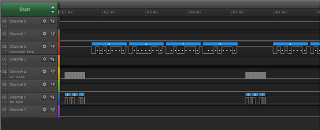
After that I started debugging and pushed the 'Start' button in saleae...Voilà!
We are transferring these simple words from our board. It means that our board has properly configured timers and is able to at least send the messages.


No comments:
Post a Comment